Tuesday, 15 July 2014

Z Axis Motor selection


The force of gravity multiplied by the mass of the Z-Axis is equal to downwards force. The motor needs to be able to hold this and lift this on a 20mm (Minor diameter: 16.5) screw with a 5mm pitch. If the force of cutting is greater than the force generated by the weight of the gantry and the need to accelerate the gantry in an upwards then this will be used in the calculations.

Force generated by Z axis = 37.12KG (2.D.P) * 9.81 = 364.1472N


http://www.esc-ltd.co.uk/Drilling%20Formulas.pdf

Fr=0.63* ((0.305*10*500)/2)= 480.375

480.375-364.1472 = 116.2278

As force is acting down upon the cutting tool from the relationship of the gantry and gravity.


L= 37.12*(2*9.81) = 728.2944N (Note: Two times gravity to allow equal acceleration in both Z directions)

Angle of  lifting plane = α
= tan^-1(Pitch/Screw minor diameter*π)
= tan^-1(5/16.5*π)
= 5.51 degree (2.D.P)

μ = 0.01 (http://www.kssballscrew.com/us/pdf/qa/Q-BS-12.pdf)

Friction Angle = β
 = tan^-1 * μ
 = tan^-1 * 0.01
= 0.57 degrees(2.D.P)

F =L tan (β + α)

   = 728.2944 * tan (0.57+5.51)
   = 77.56N (2.D.P)
  
T = F x radius
   = 77.56*0.00825 = 0.63987 Nm

The motor will require a holding force of at least 0.63987 Nm

http://www.ebay.co.uk/itm/DMM-AC-Servo-Motor-Drive-4Axis-750W-for-CNC-Router-Plasma-Mill-kit-/161346672390?pt=LH_DefaultDomain_2&hash=item259102d706

If none of the other servo motors required within the machine require more than 2nm continuous torque this should provide a good solution as it incorporates other required components.


Friday, 11 July 2014

Conceptual Designs


Design 1

This design uses a steel box section base clad with sheet steel, there are two ball screws each side driving the x axis, these are linked with a motor in the center and a pulley on either side and a timing belt. Tension on the belt is supplied by the motor sliding in its mount. The motor on the z axis is a direct drive onto a ball screw. much the same as the Y axis. The Y axis has two rails both supported round rails. The X axis has four to provide support when the X axis tries to rotate around the top rail on either side. This means that rigidity is not contained to the relationship at the top of the gantry. The whole gantry is rotated backwards to center the cutter between the carriages on the rails for the x axis in the Z direction.

The force when cutting in the X axis will be directed into X axis through a rotation of the Y axis and some force applied to the screws thus being controlled by the Y axis motor. This will create a force around the top of the gantry and the carriages on the Y axis. The only resistance to this load is the Aluminum plates that create the side of the gantry.

Out of the four designs this design scores Medium for cutting performance, Medium for ease of construction and medium in the cost category.

 Design 2


This design is primarily the same as design one however it is constructed with  aluminum frame rail for ease of construction and aluminum plates. It holds the same inherent issues as design one however is marginally weaker across the bed of the machine due to the material being aluminum as opposed to steel.

Out of the four designs this design scores Low for cutting performance, Medium-High for ease of construction and medium in the cost category.

Design 3
This design is very different from the other two, it has a single arm supported on one side. It used a singular profile rail. The intention of this design is to drastically reduce the complexity and component count thus reducing cost. It is constructed using aluminum frame rail with aluminum plates as required. However it is the weakest of all the designs. It is the easiest to construct and will be the cheapest due to the low component count.

Out of the four designs this design scores Low for cutting performance, High for ease of construction and High in the cost category.

Design 4


This design is primarily designed from square steel section that will be welded together. The tubes can be filled with an epoxy granite mix if resonance of the machine becomes a problem. The angular sections at the side are to provide support for the forces generated when cutting in the Y axis. This design will use profile rails sitting on the top of the of the frame work. This is to remove the cutting tendency for forces to rotate around the axis of the linear rail as per design one and two. Another change to this design is to fully encapsulate the spindle so it is help essentially between two gantries. These gantries will be 2 off 100x100x5mm steel box section welded together. Aluminum plate will be bolted to these to provide a fixing mechanism for rails and screws. Any welded component will be leveled off with epoxy resin to remove the effect of warping created by the heat of the welding. Although not shown there will be a removable section in the center of lower section. This will allow taller workpieces to be positioned within the machine. In this lowered section will be location stops to push the section up to. The bottom of this section will also be leveled with epoxy resin. The bed of the machine will be a thick aluminum sheet with tapped holes on a 50x50mm grid to allow mechanical fixing of components.

Out of the four designs this design scores High for cutting performance, Low for ease of construction and Low in the cost category.

Scoring Table
               

Design 1 Design 2 Design 3 Design 4
Cost  (Weighted by a factor of 2) 2 2 3 1
Ease of constuction  (Weighted by a factor of 1) 2 2 3 1
Cutting performance (Weighted by a factor of 4) 2 1 1 3
Total points 14 10 13 15

               
Design one is a very well rounded machine with reasonable performance, reasonably easy to manufacture and put together and reasonable cost.

Design two has poor cutting performance but is well rounded in other aspects

Design three has poor cutting performance however is very cost effective and very easy to manufacture and produce.

Design four, will cost the most, will be hardest to manufacture however will have have by far the best cutting performance.

Thursday, 10 July 2014

Product Design Specification


Expected product quality standards and requirements

Comparable products range in quality. Quality is not always dependent on price. Many of the lesser quality products utilise good quality mechanical components however lack a good design to utilise those components fully. However higher quality products utilise marginally substandard parts however generally have a good design lacking only in some minor areas.

This product shall use high quality products and utilise well thought out design principles to allow for highly accurate results that are repeatable and efficient.

The machine shall be finished to a high standard.

Expected product size and weight

The external dimensions of this machine shall be no larger than 2000x2000x1800mm

Weight of the machine must not weigh more than 4 tonnes.

Expected product aesthetics

The product has no aesthetics constraints, other than the machine needing to be presentable and finished to a high standard.

Expected product ergonomic requirements
 
The product will need to be designed with considerations to the ergonomics of work holding and loading of materials.


The machine has no service life considerations as it will be overbuilt beyond requirement to ensure accuracy and repeatability is suitable. It will be constructed with components with quality that in many cases exceeds that of rival commercial machines.

The machine will be required to be run from a 240v 30A domestic single phase electrical supply.

The product should be able to remove 300cc/minute of material MDF and 100cc/minute of 6061 T6 Aluminum. 

It should be able to achieve an accuracy and repeatability of +/- 0.1mm or better.

Have a working area of at least 1250x1250x200mm


The machine should be built with a design and standard that requires only minor maintenance tasks throughout its lifetime. Routine maintenance should be limited to re oiling components and tasks of such magnitude as regular tasks this should happen once a month. Other tasks such as aligning components should be much less frequent, once every 6 months.


Potential operator hazards

Around the machine the operator should wear safety glasses, a sign will be fixed to the machine to remind the operator of this requirement. The machine will also have emergency stop buttons, limit switched and other items to ensure the safety of the operator. 


All safety hazards resulting from manufacturing and assembly will be covered by the workshop risk assessment 


The machine will have the ability to stop in the event that loads become too high. With loads that are two high this indicates a problem. This will protect both the machine and the operator.


Expected product service environment

The machine shall have to operate in a temperature environment between -10 degree Celsius and +30 degree Celsius.

The machine shall have to operate in a humidity range of 30%-75%

The machine shall produce no more than 85dB of noise at a distance of 1m.

Expected product maintenance requirements

The machine will have to be oiled around once a month where required. Adjustments such as alignments and removing backlash from the machine will be performed every 6 months or as required.


All mechanical components and electrical components should be purchased as opposed to made.

Material requirements

The product must be made out of a combination of materials that allow the machine to be outside the resonance range of 800-975hz.

The machine should not deflect with a cutting load of 80N more than 50micron.

Expected product recycling potential and expected disposal

The machine should be easily recyclable or the materials used be re purposed.

Manufacturing process requirements and limitations

The machine needs to be designed so it can be produced in a “standard” machine shop. Most modern machine shops have at least 3 Axis CNC milling capability, manual lathes and manual universal milling machines.


Product packaging requirements

The machine will not need to be packaged as it is a “one off” that is not being sold

Marketing requirements and compatibility issues

As the machine will not be sold externally it has no marketing requirements.

The machine will only need to be compatible with current electrical regulations.

Monday, 7 July 2014

Spindle selection

The main types of spindle available are:

Cartridge type spindles


These require a separate motor for drive, as a result the whole assembly becomes very bulky and cumbersome however does enable the motor to be changed for varying applications or multiple motors to be added to increase torque at given RPM values.

All in one spindles


These spindles are all in one units that require power inputs, positional inputs (If acceptable) and water feeds if water cooled. This will be the type of milling spindle I will be selecting due to its compact nature and the aims and objectives of the machine. The machine will be run within a very narrow RPM range as a result a lower speed and higher torque motor for milling other materials will not be required.

The criteria set for the spindle selection are:

Must have a minimum power output of 1kw @ 19500 rpm
Must be water cooled to allow long duty cycles
Ideally should have function to facilitate automatic tool changes.

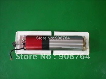
This spindle sold by JiaLing FeiLong Automation Equipments Co. LTD satisfies all the requirements other than the speed requirement. This is a maximum of 1800rpm. However I can slow the feed of the machine to compensate and increase the depth of cut to maintain material removal rate.

http://www.aliexpress.com/item/EN030-Motor-Spindle-for-CNC-milling-with-ATC/620661845.html
http://i01.i.aliimg.com/wsphoto/v0/620661845/EN030-Motor-Spindle-for-CNC-milling-with-ATC.jpg_350x350.jpg

The cost is
£2233 delivered from China.


Run out is stated at less than 3 micron

The main issue with this item is the cost.

A 2.2kw all in one spindle motor can be bought for £205

This also contains part of the electronics system to run the spindle.

http://www.ebay.co.uk/itm/200687842858

As this machine is not a production machine with the increase in price to utilize an automatic tool changer it just does not make it a viable option and a manual tool changer type spindle will have to be used.

Ballscrew accuracy and considerations


As with all components there is an accuracy value involved. Ball screws have accuracy issues with the pitch of the screw and the variance of accuracy of the central point of the channel over a length as a result of this, ball screws are rolled or ground to a specification set out my the international standards organization.


https://tech.thk.com/en/products/pdf/en_a15_011.pdf


Here is a table stating those tolerances, its probable this machine will use a 1600mm screw in both X and Y direction due to the cutting area required. This results in an error of 16 micron over the total length in regards to screw pitch. With a total travel error with a maximum of 35 micron over the full length. However it is likely that this will be less.

C3 Ball screws will be chosen from a company called true systems. In 20mm diameter and 5mm pitch these screws can withstand a force of 1130kgf. This will be more than suitable for the application of this machine. Being 20mm and hardened to the core wear characteristics will allow the life of the ball screw and nut to outlive the life of the machine.

http://www.trusystems.co.uk/wp-content/uploads/2011/03/Tru-Systems-12pp-A4-Ball-Screw-Brochure-lr.pdf

With a 2400 line rotary encoder on the servo motors should allow for a 2.01 micron resolution on a 5mm pitch screw.

Ball screw whip


The required speed on a 5mm pitch screw = 2000

Ballscrews will "whip" when at or above a certain speed, this speed can be calculated with the formula


http://www2.steinmeyer.com/content/cnt_cnt/docid_961/iso_en

nk  Critical speed [rpm]
dN  Nominal diameter [mm]
ls   Unsupported length [mm]
k   Support bearing factor

Support type

Fixed = contained in place (A motor could be a fixed support, or a support that allows no rotary movement)
Supported = supported on a bearing or similar
Free = no support

fixed - fixed: 25,5
fixed - supported: 17,7
supported - supported: 11,5
fixed - free: 3,9

dN  Nominal diameter [mm] = 16.5 (http://www.mooreinternational.co.uk/carry-ball-screw/screw20x5.html)
ls   Unsupported length [mm] =1550 (25mm each end for support)
fixed - supported arrangement (motor one end bearing on the other)


=17.7*16.5*(1/1550^2)*10^7
=1215(3SF) RPM (Not suitable for application)

A rotating nut as opposed to a rotating ball screw would enable a fixed-fixed arrangement

=1751=137 (4SF) RPM (Not suitable)

Increasing the diameter to a 25mm screw will raise the critical speed

http://www.mooreinternational.co.uk/carry-ball-screw/screw25x5.html

dN=21.5mm

nk=2282 RPM (4.S.F) This is suitable and will allow for a maximum travel speed on a 5mm pitch screw of 11.41 meters/minute without the screw whipping. 


Analysis of existing solotions

Linear motion system:


The two main drive systems are either servo motors or stepper motors.

Therefore I will compare stepper motors with servo motors subjectively to attain the best type of motor for the application.

Stepper motors vs Servo Motors:


Stepper motors
http://zone.ni.com/cms/images/devzone/ph/81947a871576.gif

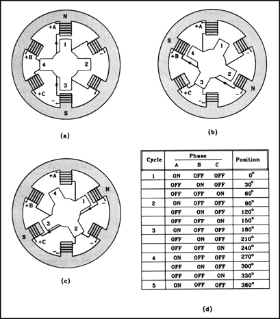
This diagram shows the stator and coil arrangement within a stepper motor. A stepper motor does at the name suggests and steps by a given amount. The diagram above shows a stepper motor with a single step consisting of 30 degrees. The stepper motors suitable for this application have many more stator and coils resulting in a single step angle of 1.8 degrees. The positioning of the rotor is relative to the coil current arrangement at that point in time. This can thus be manipulated to rotate the motor to the required position. This requires no feedback loop at the position will be dictated by the coil current arrangement.

However due to having no feed back loop if the torque supplied by the motor is less than is being resisted by whatever the motor is driving it will cause the motor to loose position. This could cause issues with part accuracy and the machine being damaged due to torque continuing to be applied despite the machine being stalled at the cutter tip.

Another issue with stepper motors is their speed torque characteristics.

http://www.anaheimautomation.com/images/stepper/torque/17Y402S%20Torque%20Curve%20(400x293).png
http://www.anaheimautomation.com/images/stepper/torque/17Y402S%20Torque%20Curve%20%28400x293%29.png


The bottom of the graph shows the speed of the motor and the torque of the motor, the vertical axis on the left shows the maximum torque of the motor at that speed. As the speed of the motor increases the torque curve drops off dramatically. With a 200 step/rev motor on a 5mm pitch screw will result in a machine resolution of 0.025mm per step. At a cutting speed of 10 meters/minute this equals 400000 steps/min 6666 & 2/3 steps per second or 33 & 1/3 revolutions per second. This will result in minimal torque at cutting speeds.

Servo Motors

Servo motors are constructed in a very similar way to stepper motors, however they have many less stator poles and poles on the rotor its self. They are rotated in the same way however due to the huge angles between potential positions generated by the stator holes they require a closed loop feedback position. Between stator poles there is an infinitely variable number of positions. This position is controlled by the current supplied to varying stator poles. This allows very fine positioning where as a stepper motor is limited to stepped positions.

http://www.anaheimautomation.com/images/brushless/torquecurve/BLZ362S-24V-3500%20Torque%20Curve%20%28400x321%29.png

This graph shows the torque/speed characteristics of a servo motor. Although as speed increases the torque decreases the curve is much flatter across the rpm range in comparison to the stepper motor.

One benefit of the stepper motor over the servo motor is the cost, generally servo motors cost more.

https://www.damencnc.com/en/components/motors-and-drivers/steppermotor/197

This is a NEMA 23 2nm stepper motor at a cost of 41.99

https://www.damencnc.com/en/components/motors-and-drivers/delta-ac-servo-motors/932

This is a servo motor that can ran at 2NM continuous load at a cost of 400


Although stepper motors are certainly less expensive, the servo motors do have the ability to stop in the event of an issue and provide better speed torque characteristics. Thus Servo motors have been chosen as opposed to stepper motors.

Guide system:
Upon analysis of the three machines 3 linear guide systems were apparent.

Round rails

http://www.zappautomation.co.uk/mechanical-products/precision-round-rail-385/sfc25-precision-round-rail.html

Cost: £36/1000mm

Supported round rails

http://www.zappautomation.co.uk/mechanical-products/precision-supported-round-rail-386/tbr20-supported-roaund-rail-32343.html

Cost: £46.20/1000mm
Profile rails

http://www.zappautomation.co.uk/mechanical-products/isel-linear-guide-rail-systems-384/linear-guid-rail-systems/lfs-8-1-linear-guide-rails-31198.html

£82.31

Round rails without support will provide little support in suitable dimensions resulting in deflection values that will affect the accuracy of the machine. Supported round rails the carriage will rotate around the axis of the rail. This will result in them not being able to suitably transmit force into the support structure they will be bolted too. A profile rail system will provide suitable support however they are the highest cost item, despite this they will be chosen as the linear guide system.

Drive mechanisms


The two main drive mechanisms are ball screws and rack and pinion from analysis of the three commercial machines.

Ball screwsBall screws have a round profile cut in a pitch along the axis of the screw, ball bearings then run in in this profile. A nut with the same profile is used. The ball bearings are then placed within the two profiles and circulated throughout the ball screw. By loading two ball screws against each other its possible to eliminate the backlash within the machine. Ballscrews are also generally very smooth along the axis, this will therefore improve surface finish and accuracy over other drive mechanisms. However ball screws do have some short comings. These include:

Requirement for design to ensure ball screws don't become contaminated.
Precision alignment during assembly


http://valuablemechanisms.files.wordpress.com/2010/05/ball-screw.gif

Rack and pinionRack and pinion is constructed as the name suggests, by running a toothed pinion and a toothed rack its possible to convert rotary motion to linear motion. There are a few ways of eliminating backlash on the rack and pinion setup. One way is to force the pinion deeper into the rack, however, this results in excess load on the motor driving the pinion and increased wear on both the rack and pinion. Another way is to run another pinion on the rack and gently apply force in the opposing direction. However, this adds complexity to the design of the machine. Also due to the increased friction other other drive mechanisms they are inefficient.

http://img.directindustry.com/images_di/photo-g/racks-pinions-20096-2786531.jpg

http://img.directindustry.com/images_di/photo-g/racks-pinions-20096-2786531.jpg

http://www.cntmotion.com/before_you_buy.html

Construction

One of the machines used aluminum profile as the main material used within the construction of the machine, others are using steel and or cast iron as the main construction material.

There are four main criteria to consider when selecting a material for a machine such as this.

Tensile strength and compressive strength
Mass and frequency damping properties  
Young modulus
Cost

As this machine is a one off machine and not a production machine, casting is not really a viable option on a one off due to the cost involved of creating tooling. Cast iron is also not readily available in sheet format for machining also much like steel it is a fairly heavy material.

Aluminum alloy is a fairly light material. Its also readily available and each to process. The machine will require all moving assemblies to be fairly light weight due to available and cost of motors. However, a structure could be created that is strong enough to withstand the forces from aluminum and transmits resonance to non moving components such as the base of the machine. The base of the machine will be made from steel as its easy to fabricate, cost effective and readily available.

Other aspects:

One of the machines has a dust extraction system, as this machine will mostly be used to machine MDF this would improve safety of use of this machine and improve the cutting operation due to less re cutting of machined material being left from the previous cutting operation or pass.

All machines seem to move the spindle and tool as opposed to the workpiece. This is to maximize the available work area within the footprint of the machine. However a fixed spindle style machine would increase strength and allow the frame to be much more substantial resulting in less resonance.

Due to the space constraints the moving spindle type machine will be required.

Saturday, 5 July 2014

Existing market solotions

First solutionCompany name: Marchant Dice Ltd

Machine model: 4' x 4' Rack and Pinion

Machine work area (mm): 1250x1250x75

Price:
£5,994

Link: http://www.worldofcnc.com/collections/cnc-router-packages/products/4-x-4-rack-and-pinion-desktop-cnc-router-package

Work area: 4'x4'x100mm

Relevant Features:
Driven by rack and pinion using stepper motors
20mm HIWIN Profile rails to allow linear motion
Aluminum profile rail construction
1900mm x 1900mm foot print
240v single phase power requirement
Dust extraction considered in design
3KW Spindle

http://i.ebayimg.com/00/$(KGrHqYOKiIE13kgypfcBNqstVI)Fw~~_12.JPG


Second solution:
Company name: signstech ltd

Machine model: 4.2ftx4.2ft CNC Router Engraver Miller
Machine work area (mm): 1300x1300x90mm
Price: £2990

Link: http://www.worldofcnc.com/collections/cnc-router-packages/products/4-x-4-rack-and-pinion-desktop-cnc-router-package

Work area: 1300x2500x90mm

Relevant Features:
Driven by ball screws ran by stepper motors
X,Z axis Round guide rail, Y axis Linear rail
Cast iron constuction
1900mm x 1900mm foot print
240v single phase power requirement
2.2KW Spindle


Third solution
Company name: Mantech UK Ltd
Machine model: JDM 25
Price: £14298
Link: http://www.ebay.co.uk/itm/CNC-Router-Engraving-Cutter-Model-M25-1300-x-2500mm-4ft-x-8ft-/170986281281?_trksid=p2054897.l4275

Work area: 1300mm x 2500mm x 200mm

Relevant Features:
1,480x3,000mm table size
0.05mm resolution
4.5KW water cooled spindle
6.34KW Total maximum power
0-24,000RPM spindle speed
Driven by stepper motors
Linear motion provided by profile rails
380v 50Hz/60HZ supply
Vacuum table holding mechanism
Dust extraction capabilities
Steel framework and steel plate construction